Desenho técnico
Características do artigo
- Max. switching voltage at safety output
- Max. switching voltage at control output
- Max. switching voltage at safety output
- Max. switching voltage at control output
- Max. switching current at safety output
- Max. switching current at control output
- Max. switching power at safety output
- Max. switching power at control output
- Max. switching power at safety output
- Max. switching power at control output
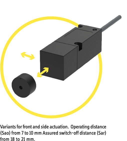
- Assured switching distance (Sao)
- Assured switch-off distance (Sar)
- Minimum switching distance (S0 min)
- Number of relay safety outputs
- Number of relay control outputs
- Stop category 0 (STO) nach IEC 61800-5-2
- Stop category 1 (SS1) nach IEC 61800-5-2
- EDM/start input
- Utilization category
- Operating voltage min.
- Operating voltage max.
- Operating voltage min.
- Operating voltage max.
- Current consumption
- Power consumption
- Power consumption
- LED display
- Switching principle
- Technology
- Min. switching voltage at safety output
- Min. switching voltage at control output
- Min. switching voltage at safety output
- Min. switching voltage at control output
- Min. switching current at safety output
- Min. switching current at control output
- Min. switching power at safety output
- Min. switching power at control output
- Min. switching power at safety output
- Min. switching power at control output
- Readiness delay (tv)
- Max no operating cycles at 0.5A switching current (ohmic load)
- Max no operating cycles at 2.5A switching current (ohmic load)
- Overvoltage category
- Pollution degree
- Protection class
- Fuse operating voltage
- Fuse safety output
- Fuse control output
- Actuation
- PL acc. to EN ISO 13849-1
- Category acc. to EN ISO 13849-1
- Coding acc. to EN ISO 14119
- Type acc. to EN ISO 14119
- Mission time in years
- Housing design
- Dimensions
- Operating speed max.
- Actuation frequency
- Free zone
- Minimum installation distance (between two sensors)
- cannot be mounted flush
- Housing material
- Cable material
- Housing colour
- Protection class
- Protection class, connector
- Operating temperature min.
- Max. operating temperature
- Min. cable temperature range, moving
- Max. cable temperature range, moving
- Min. cable temperature range, fixed installation
- Max. cable temperature range, fixed installation
- Min. storage temperature
- Max. storage temperature
- Shock resistance (Norm)
- Continuous shock resistance (Norm)
- Vibration resistance (Norm)
- Relative humidity
- Air pressure
- Delta tmax
- Mounting type
- Weight
- Possible actuators
- Cable length
- Number of strands
- Wire cross section
- Connector type
- Cable colour
- Certified in accordance with
- CE label
| Attribute | 117511E1 | 117511H1 | 117514E1 | 117611H1 | 117614E1 | 117711E1 | 117711H1 | 117714E1 | 117611E1 | 117631H1 | ED117511E1 | ED117511H1 | ED117514E1 | ED117611E1 | ED117611H1 | ED117614E1 | ED117631H1 | ED117711E1 | ED117711H1 | ED117714E1 |
|---|---|---|---|---|---|---|---|---|---|---|---|---|---|---|---|---|---|---|---|---|
| Bestellung |
|
|
|
|
|
|
|
|
|
|
|
|
|
|
|
|
|
|
|
|
| Bestellung | ||||||||||||||||||||
| Max. switching voltage at safety output | 30 V DC | 30 V DC | – | – | ||||||||||||||||
| Max. switching voltage at control output | 30 V DC | 30 V DC | – | – | ||||||||||||||||
| Max. switching voltage at safety output | 250 V AC | 250 V AC | 30 V AC | – | – | |||||||||||||||
| Max. switching voltage at control output | 250 V AC | 250 V AC | 30 V AC | – | – | |||||||||||||||
| Max. switching current at safety output | 3 A | 3 A | – | – | ||||||||||||||||
| Max. switching current at control output | 3 A | 3 A | – | – | ||||||||||||||||
| Max. switching power at safety output | 90 W | 90 W | – | – | ||||||||||||||||
| Max. switching power at control output | 90 W | 90 W | – | – | ||||||||||||||||
| Max. switching power at safety output | 750 VA | 750 VA | 90 VA | – | – | |||||||||||||||
| Max. switching power at control output | 750 VA | 750 VA | 90 VA | – | – | |||||||||||||||
| Assured switching distance (Sao) | 3 mm | 3 mm | – | – | ||||||||||||||||
| Assured switch-off distance (Sar) | 21 mm | 21 mm | – | – | ||||||||||||||||
| Minimum switching distance (S0 min) | 0.5 mm | 0.5 mm | – | – | ||||||||||||||||
| Number of relay safety outputs | 1 | 1 | – | – | ||||||||||||||||
| Number of relay control outputs | 1 | 1 | – | – | ||||||||||||||||
| Stop category 0 (STO) nach IEC 61800-5-2 | yes | yes | – | – | ||||||||||||||||
| Stop category 1 (SS1) nach IEC 61800-5-2 | no | no | – | – | ||||||||||||||||
| EDM/start input | no | no | – | – | ||||||||||||||||
| Utilization category | AC-15 / DC-13 | AC-15 / DC-13 | – | – | ||||||||||||||||
| Operating voltage min. | 21.6 V DC | – | 21.6 V DC | – | 21.6 V DC | – | 21.6 V DC | – | – | |||||||||||
| Operating voltage max. | 26.4 V DC | – | 26.4 V DC | – | 26.4 V DC | – | 26.4 V DC | – | – | |||||||||||
| Operating voltage min. | 21.6 V AC | 207 V AC | 21.6 V AC | 207 V AC | 21.6 V AC | 207 V AC | 21.6 V AC | – | – | |||||||||||
| Operating voltage max. | 26.4 V AC | 253 V AC | 26.4 V AC | 253 V AC | 26.4 V AC | 253 V AC | 26.4 V AC | – | – | |||||||||||
| Current consumption | 60 mA | 100 mA | 60 mA | 100 mA | 60 mA | 100 mA | – | – | ||||||||||||
| Power consumption | 1.5 W | 2.4 W | – | 2.4 W | – | 1.5 W | 2.4 W | – | 1.5 W | 2.4 W | – | – | ||||||||
| Power consumption | 1.5 VA | 2.4 VA | 23 VA | 2.4 VA | 23 VA | 1.5 VA | 2.4 VA | 23 VA | 1.5 VA | 2.4 VA | – | – | ||||||||
| LED display | single-coloured | single-coloured | – | – | ||||||||||||||||
| Switching principle | magnetic | magnetic | – | – | ||||||||||||||||
| Technology | Reed | Reed | – | – | ||||||||||||||||
| Min. switching voltage at safety output | 5 V DC | 10 V DC | 5 V DC | 10 V DC | 5 V DC | 10 V DC | 5 V DC | 10 V DC | – | – | ||||||||||
| Min. switching voltage at control output | 12 V DC | 10 V DC | 12 V DC | 10 V DC | 12 V DC | 10 V DC | 12 V DC | 10 V DC | – | – | ||||||||||
| Min. switching voltage at safety output | – | 10 V AC | – | 10 V AC | – | 10 V AC | – | 10 V AC | – | – | ||||||||||
| Min. switching voltage at control output | 12 V AC | 10 V AC | 12 V AC | 10 V AC | 12 V AC | 10 V AC | 12 V AC | 10 V AC | – | – | ||||||||||
| Min. switching current at safety output | 0.1 A | 0.01 A | 0.1 A | 0.01 A | 0.1 A | 0.01 A | 0.1 A | 0.01 A | – | – | ||||||||||
| Min. switching current at control output | 0.01 A | 0.01 A | – | – | ||||||||||||||||
| Min. switching power at safety output | 0.5 W | 3 W | 0.5 W | 3 W | 0.5 W | 3 W | 0.5 W | 3 W | – | – | ||||||||||
| Min. switching power at control output | 0.12 W | 3 W | 0.12 W | 3 W | 0.12 W | 3 W | 0.12 W | 3 W | – | – | ||||||||||
| Min. switching power at safety output | – | 3 VA | – | 3 VA | – | 3 VA | – | 3 VA | – | – | ||||||||||
| Min. switching power at control output | 0.12 VA | 3 VA | 0.12 VA | 3 VA | 0.12 VA | 3 VA | 0.12 VA | 3 VA | – | – | ||||||||||
| Readiness delay (tv) | 350 ms | 350 ms | – | – | ||||||||||||||||
| Max no operating cycles at 0.5A switching current (ohmic load) | 1000000 | 700000 | 1000000 | 700000 | 1000000 | 700000 | 1000000 | 700000 | – | – | ||||||||||
| Max no operating cycles at 2.5A switching current (ohmic load) | 230000 | 25000 | 230000 | 25000 | 230000 | 25000 | 230000 | 25000 | – | – | ||||||||||
| Overvoltage category | III | III | – | – | ||||||||||||||||
| Pollution degree | 2 | 2 | – | – | ||||||||||||||||
| Protection class | III | III | – | – | ||||||||||||||||
| Fuse operating voltage | 0,5A fast | 0,5A fast | – | – | ||||||||||||||||
| Fuse safety output | 3A fast | 3A fast | – | – | ||||||||||||||||
| Fuse control output | 3A fast | 3A fast | – | – | ||||||||||||||||
| Actuation | left side | front | top | front | – | – | ||||||||||||||
| PL acc. to EN ISO 13849-1 | d | e | d | e | d | e | d | e | – | – | ||||||||||
| Category acc. to EN ISO 13849-1 | 3 | 4 | 3 | 4 | 3 | 4 | 3 | 4 | – | – | ||||||||||
| Coding acc. to EN ISO 14119 | Low | Low | – | – | ||||||||||||||||
| Type acc. to EN ISO 14119 | 4 | 4 | – | – | ||||||||||||||||
| Mission time in years | 20 a | 20 a | – | – | ||||||||||||||||
| Housing design | rectangular | rectangular | – | – | ||||||||||||||||
| Dimensions | 120 x 40 x 40 mm | 120 x 40 x 40 mm | – | – | ||||||||||||||||
| Operating speed max. | 0.1 m/min | 0.1 m/min | – | – | ||||||||||||||||
| Actuation frequency | 18000 1/h | 18000 1/h | – | – | ||||||||||||||||
| Free zone | 25 mm | 25 mm | – | – | ||||||||||||||||
| Minimum installation distance (between two sensors) | 50 mm | 50 mm | – | – | ||||||||||||||||
| cannot be mounted flush | yes | yes | – | – | ||||||||||||||||
| Housing material | PBT | PBT | – | – | ||||||||||||||||
| Cable material | TPE | TPE | – | – | ||||||||||||||||
| Housing colour | schwarz | schwarz | – | – | ||||||||||||||||
| Protection class | IP67 DIN EN 60529 | IP67 DIN EN 60529 | – | – | ||||||||||||||||
| Protection class, connector | – | – | IP67 DIN EN 60529 | – | – | |||||||||||||||
| Operating temperature min. | -25 °C | -25 °C | – | – | ||||||||||||||||
| Max. operating temperature | 55 °C | 55 °C | – | – | ||||||||||||||||
| Min. cable temperature range, moving | -25 °C | -25 °C | – | – | ||||||||||||||||
| Max. cable temperature range, moving | 55 °C | 55 °C | – | – | ||||||||||||||||
| Min. cable temperature range, fixed installation | -25 °C | -25 °C | – | – | ||||||||||||||||
| Max. cable temperature range, fixed installation | 55 °C | 55 °C | – | – | ||||||||||||||||
| Min. storage temperature | -25 °C | -25 °C | – | – | ||||||||||||||||
| Max. storage temperature | 55 °C | 55 °C | – | – | ||||||||||||||||
| Shock resistance (Norm) | 30 g / 11 ms | 30 g / 11 ms | – | – | ||||||||||||||||
| Continuous shock resistance (Norm) | 10 g / 16 ms | 10 g / 16 ms | – | – | ||||||||||||||||
| Vibration resistance (Norm) | 10 ... 55 Hz | 10 ... 55 Hz | – | – | ||||||||||||||||
| Relative humidity | 5 - 85 % | 5 - 85 % | – | – | ||||||||||||||||
| Air pressure | 860 - 1060 hPa | 860 - 1060 hPa | – | – | ||||||||||||||||
| Delta tmax | 0.5 °C/min | 0.5 °C/min | – | – | ||||||||||||||||
| Mounting type | screwed | screwed | – | – | ||||||||||||||||
| Weight | 500 g | 500 g | – | – | ||||||||||||||||
| Possible actuators | 30427102 | 30427102 | – | – | ||||||||||||||||
| Cable length | 1 m | 1 m | – | – | ||||||||||||||||
| Number of strands | 5 | 5 | – | – | ||||||||||||||||
| Wire cross section | 0.75 mm² | 0.75 mm² | – | – | ||||||||||||||||
| Connector type | – | – | M12x1 - 5 polig | – | – | |||||||||||||||
| Cable colour | silbergrau | silbergrau | – | – | ||||||||||||||||
| Certified in accordance with | EN ISO 13849-1 UL 508 / CSA 22.2 | EN ISO 13849-1 UL 508 / CSA 22.2 | – | – | ||||||||||||||||
| CE label | yes | yes | – | – | ||||||||||||||||


