Sensors - General information


To choose the right magnet, you need to know: – minimum switching distance – maximum switching distance – ambient temperature – installation space for the magnet – sensor to be used (AW area of the reed switch)
Do not mount solenoid switches directly on magnetically conductive (ferritic) material. Magnets may be placed along the polarisation axis directly on ferritic material. Once the switching points are fixed, if the conditions remain the same there will be minimal variation. Temperature-dependent changes are minimal. Example: For AlNiCo material, a shift in switching point of 0.05 mm is typical for a temperature change of 20°.
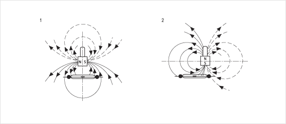
Schematic representation of the magnetic field lines with varying orientation of the magnetisation axis to the switch.
Note: With reed contacts, an especially short hysteresis can be achieved if the polarisation axis is normal to the longitudinal switch axis and the movement direction of the magnet for opening the contact is towards the middle of the switch (overlapping of the contact blades).

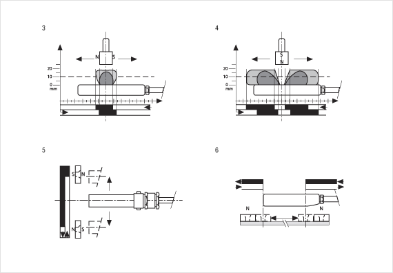
Magnet actuation with reed contacts and differently polarised magnets.
When passing over the switch in the lengthwise direction, two or even three switching points are possible. If the magnet passes completely over the switch, the switch should be actuated from the front or the movement direction should be transverse to the lengthwise axis of the switch.
With an arrangement as shown in figure 1, rotating magnets can be used to achieve a simple rotary pulse generator (two pulses per/rotation).
Figure 3: depending on the distance between switch and magnet, it is possible to have either three switching points or just one.
Figure 4: with this type of actuation, there are two switching points. With bi-stable contacts, a latching switch that is dependent on either magnet polarity or direction of movement can be set or cleared.
Figure 5: shows magnet-polarity-dependent control. The direction of movement has no influence.
Figure 6: switch actuation is dependent on the direction of movement. Shown in the example is a movable carrier that carries the adjustably arranged magnets. It is moved back and forth between two (adjustable) end points.


Product has been added to watchlist.